Getting into SMD fabricating has really opened the doors to all sorts of new ideas.
My first attempt at a wearable was sort of inspired in part by FLORA and the other wearable stuff at AdaFruit.
It's a 1 inch diameter board with 8 SMD LEDs mounted equidistantly around the outer edge. Each is hooked up to a digital pin on an ATTiny84. There's also a micro-switch input to the controller and the whole thing is powered by a CR1225 battery. A pair of them would be a pair of earrings.
Here, the purple color of OSH Park's boards is actually a good thing - the hope is that the actual earrings themselves are dark and unobtrusive, or at least as much as they can be. The usual garish green solder mask color would be awful in comparison.
The button will be used to select different blink patterns.
It's asking a lot for a CR1225 to drive even a single LED, so although the board was designed with series resistors for each LED, the initial prototype is going to be stuffed with "0 ohm" parts. The blink patterns are going to be designed so that only a single LED is on at once.
The real question is still going to be whether it's going to work at all. The risk is that pulsing the LED will cause the voltage from the battery to drop enough that it hoses the controller. I don't know what I would do to fix it, though, because there isn't room for something bigger, like a CR2032.
But the larger point here is that with through-hole versions of these components, there's just no way this would be even worthy of consideration.
I got the SMD LEDs in the mail today and broke a couple out to try them with a pair of AA batteries. I probably overdrove them a little, but they were quite bright.
We'll see.
Saturday, November 30, 2013
Friday, November 29, 2013
Toast-R-Reflow: revised schematics
I've revised the schematics a bit. First, the power board:

The controller:

The change here is that a bunch of passive components have been added to the thermocouple input. There is a 1M resistor from the negative pin to ground. I'm not 100% sure why, but it's what the data sheet recommends. The RC network on the thermocouple pins is recommended to prevent RF from affecting the readings. Other than that, it's the same.
Thursday, November 28, 2013
Toast-R-Reflow: how-to summary
This is intended to be a sort of "landing page" that summarizes the Toast-R-Reflow project. Now that you're here, you can do a deeper dive by checking out all of the posts here with the toast-r-reflow label.
The internet is full of folks who have made their own SMD reflow oven by hacking a toaster oven. I'm not the first, and certainly won't be the last. The reason you have to hack them at all is because the controls that come with these devices are not nearly precise enough to follow a reflow soldering profile. Gutting the controls that come with the oven and giving control of the heating elements to a microcontroller (like an Arduino), and providing that controller with the ability to read the temperature from a high-temperature rated thermocouple is the task at hand.
Oven heating elements run with AC line voltage power and require hundreds of watts of electrical power. In order for a microcontroller to safely control such a load, it must be galvanically isolated. Most folks have used a Solid-state relay to do the switching, but those are very expensive. Triacs have been around for a long time now, and some are quite hefty. They can be controlled by opto-isolated driver triacs quite simply, with the result that the entire high-voltage switching assembly can be made on one board and built inside the oven where the original user controls were located. The input side of the optoisolator can be wired to low voltage wires and routed outside to the controller with complete safety. The triac circuit is inexpensive and simple enough that putting two copies of it on the board made it possible to cut the current requirements in half (so long as you can divide the load evenly between the two sides). The design is rated for 8 amps per channel, or just short of 2000 watts of power combined.
Lots of folks have bought a commercial PID controller to operate their oven. A PID controller is designed to provide an analog control signal, but that can be easily translated into a digital control signal by using a slow version of PWM. The Arduino has facilities for automatic PWM, but we're talking about a pulse frequency of closer to 1 Hz - much easier to simply do it in software. It should be noted that this is how microwave ovens provide proportional power as well - when you ask for 50% power, the microwave will generate power for one second and then stop for one second. This mechanism makes element control quite easy - you just need to be able to turn them on and off. Commercial PID controllers are also, however, quite expensive. Adapting an Arduino or - even better - an Atmel ATTiny controller to do the job can be done quite inexpensively. I started down this road by breadboarding the controller and designing the permanent controller as an SMD board. The power board was made with through-hole components simply because there are aren't many components and they need to have high voltage ratings. It also served to solve the bootstrapping problem - you build the power board, convert the oven and run the cycles at first with an Arduino and/or breadboarded controller, then use that to reflow the permanent controller.
For a while now, I've been using the OpenEVSE store's 2 line RGB LCD for just about everything. They're the same as the AdaFruit RGB LCD shield, but arranged as a "backpack" design with a 4 pin SIP cable connection back to the controller board. The particularly nice thing about these displays is that you can see the backlight color from much further away than you can read the text, which is useful for simple status reporting. The backpack/shield also allows you to read 5 buttons (we will only need one as a 'start' button) all over a single i2c slave.
The thermocouple needs a cold junction compensated amplifier. There are quite a few of those out there to choose from. The AD8495 is the best answer in terms of cost and simplicity. The original breadboard prototype was made with an AD595AQ, which is an older device and 3 times more expensive. To make the breadboarding easier on the next guy to come along, I designed an AD8495 breakout board that can plug into a breadboard and has a pair of screw terminals for a K type thermocouple. The AD8495 simply outputs a voltage that is 5 mV for every °C. This can be fed directly into an Arduino / ATTiny analog pin and read with analogRead() and scaled appropriately. +/- 1 °C is fine for this application.
Finally, an ATTiny85 is a perfect choice for the controller. It has a USI interface that can be converted into i2c with the TinyWireM library, and it has besides that two digital pins and one analog input pin - exactly what we need.
As for the oven, a Hamilton-Beach 31138 from Fry's was what I more or less randomly chose. It turned out to be an excellent choice. It can keep up with the reflow profile I chose and has yielded quite good results. It was also easy to disassemble and convert to its new use.
I'll be stocking the power and controller boards in my store if anyone wants to follow in my footsteps. The firmware for the controller is over on GitHub.
Toast-R-Reflow: the bottom line
The power board is rated for 8 amps per channel. That limitation is a factor of two things - the traces on the power board that connect the oven's innards to the traics, and the ability of the triacs and heat sinks to dissipate heat. According to the data sheet of the BTA-20 triac, at 8 amps, it generates 10 watts of thermal power. The case-to-mounting-tab is rated at 2.1 °C/W. The heatsink I chose has a rating of 5 °C/W. So 7.1 * 10 is 71 °C temperature rise at rated power. The maximum junction temperature is 125 °C, so that means that the maximum ambient temperature for the power board is 50 °C, or 122 °F. I stuck a thermometer in one of the vents and ran a cycle and the temperature near the heatsinks never rose above 100, let alone above 122. That's a bit of a surprise, given that that chamber is right next to an uninsulated metal box being heated internally to 225 °C. Credit the ventilation, I guess. Undoubtedly it's so liberally ventilated to insure that the original user controls remain cool to the touch during use.
As for the traces on the power board, they're a minimum of .1 inches wide at the thinnest point, and they're on both sides of the board. OSH Park's boards use 1 oz copper. Since we're using both sides, that's either an equivalent of 2 oz copper or .2 inches wide, take your pick. Plug those into this calculator and you get that a maximum current of 8 amps requires 104 mils of trace width with 2 oz copper on external (air facing) traces. Most of the current-bearing traces are wider than that, but it does become quite narrow right where the triac pins are.
The boards are $7.50 each from OSH Park. The BOM from DigiKey is just under $10, plus shipping and tax. I took a look at DigiKey's catalog, and there are SSRs they stock that are competitive with this design, but they don't blow it away in either price or performance, and the best option I found would have been more difficult to deal with from a thermal perspective. Standalone SSRs, like those I've seen people use on the Internet, are many times more expensive.
The controller boards are $4 each from OSH Park. The BOM is $12. You also need an OpenEVSE RGB display backpack, which sells for $35. And the oven was $40. So, in short, the whole thing was around $115.
Reflow oven safety
When converting a toaster oven or skillet into a reflow appliance, some thought must be given to safety. There are obvious safety precautions concerning line voltage and heat, but one you may not think about is the fact that you started with an appliance meant for treating human food.
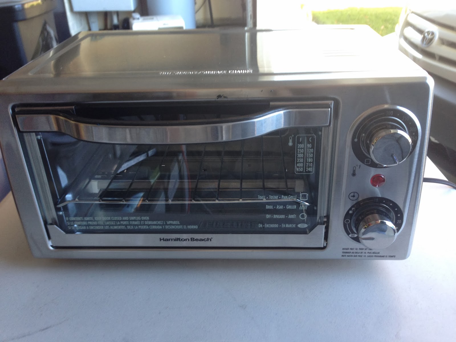
Even if you use RoHS solder paste, the flux is nasty stuff and it vaporizes. You can count on it getting everywhere the first time you use it. In short, once used for reflow, you must never again use it for food. And that means anyone who might come across it. Some day you will throw the oven away. You don't want someone to find it and try to repair it and put it back to use as a toaster.
So I liberally wrote on mine with a sharpie. The handwriting is bad, but hopefully the message is plain and will survive until the oven is reduced to scrap.

You'll notice that the original controls are still there. I just didn't bother to remove them, but they aren't connected to anything and don't work. The light doesn't light up anymore.
The low voltage wires just come out of one of the vents, but that's ok. The worst that could happen is that they short out and draw 30 mA of 5 volts or so.
The SMD adventure begins in earnest
Ordered my first bulk order of SMD parts from DigiKey last night. 0805 1/8W resistors are 10 cents a piece in single unit quantities (plus, like, $3 shipping), but a reel of 5000 of them is only $15. And for me, that's easily a lifetime supply.
I waited until now because I wanted to get some experience with the reflow oven before committing to it as the path forward.
I can now say with some certainty that the 1.6 version of the Hydra will be the last through-hole design. Same with the current version of the EV Sim 2.
So what do you buy when starting out?
Well, first and foremost, 0.1 uF 50V 0805 ceramic capacitors. Every chip needs at least one mounted nearby across its power supply pins. Next, 330 ohm resistors. They're series resistors for NPN transistors and LEDs. 10K resistors for the pull-up on !RESET for every AVR controller.
I also got some parts to flesh out the reflow oven controller - I suspect I may sell a few of those. For them, I need the rest of the passive parts for the AD8495 thermocouple amp - 1M, 0.01uF. Also, 0.33 uF for the regulator. I also got a tape of regulators, input protection diodes and Tiny85s.
My big problem right now is firmware. I've got a number of ideas for the Tiny85, but they all involve driving a 2 line LCD display over i2c. TinyWireM, LiquidTWI2 and the Arduino core by themselves seem to take up most of the available flash! I can't hardly believe that's true. I've got to look into it to see where all the space is going.
Wednesday, November 27, 2013
Toast-R-Reflow: First success
I got the power board installed in the oven without too much difficulty.


This is a picture of the mounting for the power board. I drilled 4 holes in the outer sheet metal enclosure. There was a blank spot near the top (the piece is shown here upside down) where there were no ventilation holes (you don't want to be able to accidentally poke something through a vent and touch a high-voltage PCB trace) and mounted the board there. I got lazy and just shoved the 3 low-voltage wires through a vent slot nearby. I had planned on mounting a grommet, but I got lazy.

This is a view with the top put into position enough to actually attach the wires. The hot line got re-crimped with a new QD connector because the original one was the .178" size and it wouldn't fit the terminals I had mounted on the board.
If the heatsinks look a little funky, it's because it's the prototype board. I didn't properly place holes for the pins on the heatsink to sit in, and the triacs aren't perfectly positioned. The boards that are in the store now are better, but these will do for now for me.
As for the thermocouple, I just ran that through the side of the door. This lets me position it nearby the board every time I get ready. I might come up with a better solution later.
The first board that was processed by the oven was an EV Sim Mark II SMD board.
I used a template and some ChipQuik paste. It was an absolute mess. I am fairly certain that I'm not using the template right. I wound up with sort of "blobs" on the pads and in the area surrounding each. I decided to give it my best shot.
And it worked!

Every part you see there except for the through-hole components and the two parts I had to rework (the protection diode was backwards - the label was very hard to read, and the power jack has a boss that doesn't match up with the hole where it's supposed to land. I had to lop it off with an Xacto knife and resolder it), every part was "nudged" into a blob of paste and the oven took it from there. Most of the parts weren't even completely straight, but the magic of surface tension fixed that.
What's more, I was able to program the controller without mounting the through-hole ISP socket. I got a Pogo ISP adapter from SparkFun, and this was my first opportunity to use that as well, and it also worked perfectly. I went ahead and mounted the through-hole socket anyway, because this is going to wind up in the store, but at least for my own projects, I may not bother anymore.
I'm going to try to do the other two EV Sim II boards that I got in that OSH Park order tomorrow. If those work as well as this one did, then the next step will be for the oven to reflow its own permanent controller board. And that will happen as soon as those boards come back from OSH Park.
Tuesday, November 26, 2013
Toast-R-Reflow: Initial success
The power board prototypes arrived today. I built one out and connected it up to the oven. It works perfectly.
I fed it with a 5 volt power supply and a 200 ohm resistor and it turned the elements on and off like a perfect light switch. I left it on long enough for the elements to glow red hot and then quickly unplugged everything and checked the triac heat sinks and they were cold. I've now got no doubts at all that it's going to work. Next step will be to build it into the oven and button everything up.
Anyone who wants to follow along should now feel confident in getting their own power board from OSHPark. You can find the design here. It's $22.40 for 3 copies of the board, but I'll sell them in single quantities in my store.
The power board is designed to switch up to 8 amps per channel (this is based on the width of the current carrying traces on the board and the heat capacity of the heat sink). As long as you can split the load in half, you should have no trouble switching 1500 watts.
To use it, you bolt a QD male terminal onto each of the 3 large holes in the middle of the board. The centered one connects to the hot lead of the AC input, and the other two go to the load - in this case each of the two heating elements in the oven.
The 3 terminal block at the end of the board has a common cathode pin and an anode pin for each of the two channels. You must use current limiting resistors on each anode line. The LED in the opto-isolators is rated for 30 mA with a forward voltage drop of 1.5 volts. Make sure you do not exceed the opto-isolator's maximum current rating of 50 mA. You should have no trouble driving them with an AVR digital pin directly with just a current limiting resistor in series.
Monday, November 25, 2013
The irritating thing about hardware design
Being a software guy by nature, I'm used to very rapid design and implementation turnaround. You edit the source code, compile it, upload it, try it, find bugs, lather, rinse, repeat.
What's chafing my hide now that I'm doing hardware projects is that the turnaround time to get a PCB fabricated is 2 weeks.
All I can do in that 2 weeks is obsessively go over the design that I've already paid for. Sometimes I wind up finding a whopper of a mistake and have to order a new design. Then I still get to wait a week to receive a package in the mail with my mistakes in it. I open the envelope, smirk, and throw the boards right in the trash. It's disconcerting.
My latest mistake is that I thought a particular part that I want to use was some sort of narrow variant of a SOIC-8 package. Um, no, it's an MSOP-8. It's much smaller. There's no way the leads are going to fit the pads on the board. So the first two versions of the Toast-R-Reflow controller that I've ordered are all garbage.
Saturday, November 23, 2013
Toast-R-Reflow theory of operation
If anyone cares to know how the Toast-R-Reflow actually works, it goes something like this:
The power board consists of a pair of MOC3020 photo-triac drivers, each triggering the gate of a BTA20 high current triac. The MOC3020s are directly connected to a set of screw terminals intended to be run to the logic board, which will be expected to provide the correct driver voltage and current for the LEDs.
The actual triac circuit is straight out of the datasheet. I confess I am not 100% sure of the purpose of each of the parts beyond the optoisolators, but each of the triac drivers is rated for 8 amps of current (this rating is due mainly to the width of the traces on the board running to the triac pins and the heatsinks' ability to get the heat out of the triacs when they're installed next to a box being heated to 225 °C). This means that if you can drive the two elements separately, you can handle up to 1920 watts of power, which should be plenty for a consumer grade toaster oven or hotplate.
The controller board has an AD8495 thermocouple amplifier on it. This amplifier outputs a voltage of 5 mV per °C detected on the thermocouple. This voltage is fed into analog pin 3 on the ATTiny controller. Two of the pins of the ATTiny are used as the i2c bus to drive the external 2 line RGB display, which also as a side effect handles the start button. Two of the other pins of the ATTiny are power and one is RESET, which leaves us with two digital out pins that we can send off to the power board (going through 150 ohm resistors first in order to produce the correct LED driver current).
The software uses the Arduino PID library to turn the elements on and off with a sort of exaggerated PWM method. The PID will output a floating point number between 0 and 1000, and that's the number of milliseconds out of each second that the elements will be powered (this is similar to how microwave ovens deliver fractional power). The sketch will attempt to turn the elements on separately, so that if the duty cycle is 50% or less, they won't be on at the same time, which will reduce the instantaneous power draw somewhat.
One point of note is that the one of the pins of the controller used for programming is also one of the element control lines. This means that that line will have a great deal of random activity during programming. Because of this, it's important to make sure the oven is unplugged during programming, otherwise you'll be pulsing the elements randomly and they could conceivably overheat.
I beat SparkFun! :)
SparkFun sells a small board that will adapt a 6 and 10 pin AVR ISP connector to a breadboard. I had been using a special cable that I made with a 14 pin DIP IDP plug on one end and the 10 pin 2x5 IDP socket on the other end. That works because the DIP plug can split the center channel of a breadboard. But I do think that SparkFun's answer is a touch cleaner. What bugged me was the prospect of a 95 cent order with, like, $2 in shipping. So I sat down with Eagle and at the end of the day I made a design that costs $2.80 for a batch of 3 (so 93.3¢ each and free shipping) from OSH Park! That works out nicely because it means that I can permanently breadboard an ATTiny85, an ATTiny84 and an ATMega328P all at the same time for prototyping and pick the appropriate one for the design I'm working on. Each can have the power supply (with bypass cap), an i2c bus connection to a display shield, and ISP all ready to go - sort of like a poor man's Arduino.
If you want a batch of them, they're here.
If you want a batch of them, they're here.
Wednesday, November 20, 2013
Toast-R-Reflow timing
I got a better thermocouple today, so I tried the timing test again.
This time, 20-150°C took 2:22. 150-225 took 2:34, then back down to 150 took 1:50. Cooling down from 150 took longer than I cared to time, but that doesn't really matter so much.
So that means rising up to Soak is at just under 1 degree per second. Rising up from Soak to Reflow happens at just under half a degree per second. Falling from Soak happens at just under 3/4 of a degree per second.
Sunday, November 17, 2013
Toast-R-Reflow schematics
Here are the schematics for the two boards that comprise the Toast-R-Reflow project.

This is the controller board. In the upper left corner is the thermocouple amplifier. Below that is the 5 volt power supply. The input jack is a standard 2.1mm barrel connector. The rest of the circuit is the micro controller and its I/O. In essence, the controller takes in the temperature from the thermocouple and controls two digital output lines that go off to the other circuit (below). There are 330 ohm resistors on those two lines because they're intended to drive an optoisolator input, meaning that you want around 20 mA of current or so - enough to light up an LED. There is an i2c connector on the board that leads off to an OpenEVSE or AdaFruit RGB LCD backpack/shield, which is also how we get a pushbutton input (used to start the reflow process).

This is the power board. It's a separate board because it has 120 volt power running through it. Note that the path from the hot terminal through the triacs and to the output terminals are specified to carry up to 750 watts of power, so they're going to need to be very wide traces on both sides of the board.
The triacs are also going to need fairly substantial heat sinks. Even more so because they're going to be in proximity to the actual heated space of the oven. I think we can safely assume an ambient temperature of 50 degrees C, at least. The triac data sheet says that at the design current, we can expect it to dissipate 10 watts of thermal energy. The heatsinks I've ordered have a 5 degrees C per watt rating. Combined with the triac mounting terminal spec, the online calculators I've seen suggest that this ought to be a combination that should be acceptable.
The power board is a separate board so that it can be built-in to the oven. The two isolator input lines and ground can safely be routed out of the oven to the controller board, along with the thermocouple cable.
The three large terminals on the schematic are actually in the SparkFun electro-mechanical eagle library. They're #4 holes designed to be electrically connected. #4-40 hardware will be used to attach QD male connectors directly on the board. The QD female connectors on the wires of the oven will plug right in.
Introducing... Toast-R-Reflow
I've been really into microcontroller engineering of late. I've created the J1772 Hydra, and the EV Sim Mark II as well as a whole bunch of little experiments.
I attempted to build a surface-mount version of the EV Sim II, and hand soldering all of those tiny little parts was a painful exercise. I was going to give up on the idea, but I was turned on to the concept of reflow soldering.
In a nutshell, you get a circuit board fabbed just the same way as always. I use Eagle as my CAD software. OSH Park is my board fab of choice, and they'll take an Eagle .brd file as source material.
Next, you must create an SMD pad template file. You do this by exporting the "cream" layer from Eagle as a Gerber file. The file is a description of all of the places where soldering will be taking place. You send that off to Pololu and have them make you a paste template.
The next step is similar to silk-screening a T shirt. The template is a sheet of plastic with laser-cut holes where the Eagle "cream" layer had them. You anchor that template on top of the board with all of the pads and template holes lined up. You then apply reflow soldering paste to the template and use a metal squeegee (I'm going to use a spackle knife) to scrape it off the template surface, leaving only the holes filled in.
After removing the template, now you have paste applied to all of the pads. The paste, I am told (I haven't yet done this), is like wet cement. You use tweezers to place all of the parts and "smoosh" them into the paste slightly. The paste will hold them in place while this is going on. The "Big Boys" use pick-n-place robots to do this work.
Once the parts are all in place, you carefully move the board into a reflow oven. The oven will heat up, very precisely following a specific time-temperature profile. It will gradually heat the entire assembly up to 150 degrees C, then hold the temperature there for a minute and a half, then as quickly as possible it will crank up to 225 degrees C and hold that for 30 seconds. That will be hot enough to activate the flux in the paste, which will clean the pads and parts, and then melt the solder, causing it to "flow" to the pads and parts. Finally, the oven cools, but no more quickly than allowed lest the parts suffer from thermal shock.
Commercial reflow ovens are outrageously expensive. That's to be expected with a low volume piece of commercial equipment. But lots of hobbyists have built their own reflow ovens by modifying toaster ovens to add microcontroller-based heating control with thermocouple temperature monitoring (all of this in the interests of increased precision). I've decided to go down this road too. None of the approaches taken by any of the other Internet hobbyists I've discovered look to me like they're... optimal somehow. Some of them build the entire retrofit into the oven, which looks excessively complicated to me, and others externalize the entire mod, which seems less safe to me. Most folks buy a solid-state relay, which is outrageously expensive. For less than a quarter the cost, I designed and purchased the parts for a triac-based opto-isolated power switching board. That board will be built inside the oven. The OEM controls will all be ripped out and the elements and hot line from the AC plug will be connected instead to the board, and the board installed in place of the original stuff. The optoisolator inputs will be connect to to a cable running out (along with the thermocouple cable) to the controller board. I've designed a small controller board (ironically, it's made with SMD parts) with an ATTiny 85 and an AD8459 thermocouple amplifier. I'm fairly confident that I could productize the two boards as a "conversion kit" for around $30 (add a 2 line LCD display and i2c "backpack" board, a button, a thermocouple and a toaster oven).
While I was ordering the parts, I bought a thermocouple probe and amplifier chip. I then went to Fry's and bought a Hamilton Beach model 31138. From examining it on the shelf, it looks like it's going to be reasonably easy to disassemble and modify. But before I make it impossible to return, I wanted to test it. I put the thermocouple in the oven and set it to 450 and turned it on.

It took 90 seconds to get to 50 degrees (all measurements are in Celsius. I'm going to stop saying that now), a further 67 seconds to get to 100, 78 more seconds to get to 150, 96 more seconds to get to 200 and then 63 seconds to get to 225. I turned off the heat at that point and the oven took 4:50 to fall down to 150 degrees.
At first glance, that doesn't look like very good performance, but the slow cooling has made me think that the problem is that the thermocouple is not agile enough. So I'm going to get a different one (this time not embedded in a big metal probe) and try again.
Meanwhile, I decided to go for broke. The oven is very easy to disassemble with just a philips screwdriver.


There is a single piece of sheet stainless steel wrapped around the sides and top of the oven. You need to pull all of the screws on the back that hold this piece in place. There's one screw near the left (viewed from the front) rear bottom that also must be removed. Next, pop out the rubber inserts in each of the plastic feet and unscrew and remove the screws inside as well as the two larger philips screws between the feet. That done, the top/side sheet should pop right off.
Once that's done, cut and remove the two "rat belts" bundling the wires near the AC plug and near the top. Use a flat screwdriver and pop the QD connectors (each is inside a redish-brown rubber heat shield) attaching all of the wires to the controls. You'll wind up with one coming from the top element, one coming from the bottom element, and one coming from the hot line of the AC plug. There are some other QDs, but they won't be used.
I attempted to build a surface-mount version of the EV Sim II, and hand soldering all of those tiny little parts was a painful exercise. I was going to give up on the idea, but I was turned on to the concept of reflow soldering.
In a nutshell, you get a circuit board fabbed just the same way as always. I use Eagle as my CAD software. OSH Park is my board fab of choice, and they'll take an Eagle .brd file as source material.
Next, you must create an SMD pad template file. You do this by exporting the "cream" layer from Eagle as a Gerber file. The file is a description of all of the places where soldering will be taking place. You send that off to Pololu and have them make you a paste template.
The next step is similar to silk-screening a T shirt. The template is a sheet of plastic with laser-cut holes where the Eagle "cream" layer had them. You anchor that template on top of the board with all of the pads and template holes lined up. You then apply reflow soldering paste to the template and use a metal squeegee (I'm going to use a spackle knife) to scrape it off the template surface, leaving only the holes filled in.
After removing the template, now you have paste applied to all of the pads. The paste, I am told (I haven't yet done this), is like wet cement. You use tweezers to place all of the parts and "smoosh" them into the paste slightly. The paste will hold them in place while this is going on. The "Big Boys" use pick-n-place robots to do this work.
Once the parts are all in place, you carefully move the board into a reflow oven. The oven will heat up, very precisely following a specific time-temperature profile. It will gradually heat the entire assembly up to 150 degrees C, then hold the temperature there for a minute and a half, then as quickly as possible it will crank up to 225 degrees C and hold that for 30 seconds. That will be hot enough to activate the flux in the paste, which will clean the pads and parts, and then melt the solder, causing it to "flow" to the pads and parts. Finally, the oven cools, but no more quickly than allowed lest the parts suffer from thermal shock.
Commercial reflow ovens are outrageously expensive. That's to be expected with a low volume piece of commercial equipment. But lots of hobbyists have built their own reflow ovens by modifying toaster ovens to add microcontroller-based heating control with thermocouple temperature monitoring (all of this in the interests of increased precision). I've decided to go down this road too. None of the approaches taken by any of the other Internet hobbyists I've discovered look to me like they're... optimal somehow. Some of them build the entire retrofit into the oven, which looks excessively complicated to me, and others externalize the entire mod, which seems less safe to me. Most folks buy a solid-state relay, which is outrageously expensive. For less than a quarter the cost, I designed and purchased the parts for a triac-based opto-isolated power switching board. That board will be built inside the oven. The OEM controls will all be ripped out and the elements and hot line from the AC plug will be connected instead to the board, and the board installed in place of the original stuff. The optoisolator inputs will be connect to to a cable running out (along with the thermocouple cable) to the controller board. I've designed a small controller board (ironically, it's made with SMD parts) with an ATTiny 85 and an AD8459 thermocouple amplifier. I'm fairly confident that I could productize the two boards as a "conversion kit" for around $30 (add a 2 line LCD display and i2c "backpack" board, a button, a thermocouple and a toaster oven).
While I was ordering the parts, I bought a thermocouple probe and amplifier chip. I then went to Fry's and bought a Hamilton Beach model 31138. From examining it on the shelf, it looks like it's going to be reasonably easy to disassemble and modify. But before I make it impossible to return, I wanted to test it. I put the thermocouple in the oven and set it to 450 and turned it on.
It took 90 seconds to get to 50 degrees (all measurements are in Celsius. I'm going to stop saying that now), a further 67 seconds to get to 100, 78 more seconds to get to 150, 96 more seconds to get to 200 and then 63 seconds to get to 225. I turned off the heat at that point and the oven took 4:50 to fall down to 150 degrees.
At first glance, that doesn't look like very good performance, but the slow cooling has made me think that the problem is that the thermocouple is not agile enough. So I'm going to get a different one (this time not embedded in a big metal probe) and try again.
Meanwhile, I decided to go for broke. The oven is very easy to disassemble with just a philips screwdriver.


The left inside - the front is to the right.

The right inside, where the controls are.

Here are the wires of interest: red is hot, white is top element, blue is bottom. The rest don't matter.

Check the wiring... The hot line goes directly to the red QD on the table. The neutral line goes to the indicator light on the front panel and to the two elements on the far side of the oven. We won't bother hooking the hot side of the light to anything, so those two QDs will be wrapped in tape to keep them out of mischief.
There is a single piece of sheet stainless steel wrapped around the sides and top of the oven. You need to pull all of the screws on the back that hold this piece in place. There's one screw near the left (viewed from the front) rear bottom that also must be removed. Next, pop out the rubber inserts in each of the plastic feet and unscrew and remove the screws inside as well as the two larger philips screws between the feet. That done, the top/side sheet should pop right off.
Once that's done, cut and remove the two "rat belts" bundling the wires near the AC plug and near the top. Use a flat screwdriver and pop the QD connectors (each is inside a redish-brown rubber heat shield) attaching all of the wires to the controls. You'll wind up with one coming from the top element, one coming from the bottom element, and one coming from the hot line of the AC plug. There are some other QDs, but they won't be used.
Subscribe to:
Posts (Atom)