I attempted to build a surface-mount version of the EV Sim II, and hand soldering all of those tiny little parts was a painful exercise. I was going to give up on the idea, but I was turned on to the concept of reflow soldering.
In a nutshell, you get a circuit board fabbed just the same way as always. I use Eagle as my CAD software. OSH Park is my board fab of choice, and they'll take an Eagle .brd file as source material.
Next, you must create an SMD pad template file. You do this by exporting the "cream" layer from Eagle as a Gerber file. The file is a description of all of the places where soldering will be taking place. You send that off to Pololu and have them make you a paste template.
The next step is similar to silk-screening a T shirt. The template is a sheet of plastic with laser-cut holes where the Eagle "cream" layer had them. You anchor that template on top of the board with all of the pads and template holes lined up. You then apply reflow soldering paste to the template and use a metal squeegee (I'm going to use a spackle knife) to scrape it off the template surface, leaving only the holes filled in.
After removing the template, now you have paste applied to all of the pads. The paste, I am told (I haven't yet done this), is like wet cement. You use tweezers to place all of the parts and "smoosh" them into the paste slightly. The paste will hold them in place while this is going on. The "Big Boys" use pick-n-place robots to do this work.
Once the parts are all in place, you carefully move the board into a reflow oven. The oven will heat up, very precisely following a specific time-temperature profile. It will gradually heat the entire assembly up to 150 degrees C, then hold the temperature there for a minute and a half, then as quickly as possible it will crank up to 225 degrees C and hold that for 30 seconds. That will be hot enough to activate the flux in the paste, which will clean the pads and parts, and then melt the solder, causing it to "flow" to the pads and parts. Finally, the oven cools, but no more quickly than allowed lest the parts suffer from thermal shock.
Commercial reflow ovens are outrageously expensive. That's to be expected with a low volume piece of commercial equipment. But lots of hobbyists have built their own reflow ovens by modifying toaster ovens to add microcontroller-based heating control with thermocouple temperature monitoring (all of this in the interests of increased precision). I've decided to go down this road too. None of the approaches taken by any of the other Internet hobbyists I've discovered look to me like they're... optimal somehow. Some of them build the entire retrofit into the oven, which looks excessively complicated to me, and others externalize the entire mod, which seems less safe to me. Most folks buy a solid-state relay, which is outrageously expensive. For less than a quarter the cost, I designed and purchased the parts for a triac-based opto-isolated power switching board. That board will be built inside the oven. The OEM controls will all be ripped out and the elements and hot line from the AC plug will be connected instead to the board, and the board installed in place of the original stuff. The optoisolator inputs will be connect to to a cable running out (along with the thermocouple cable) to the controller board. I've designed a small controller board (ironically, it's made with SMD parts) with an ATTiny 85 and an AD8459 thermocouple amplifier. I'm fairly confident that I could productize the two boards as a "conversion kit" for around $30 (add a 2 line LCD display and i2c "backpack" board, a button, a thermocouple and a toaster oven).
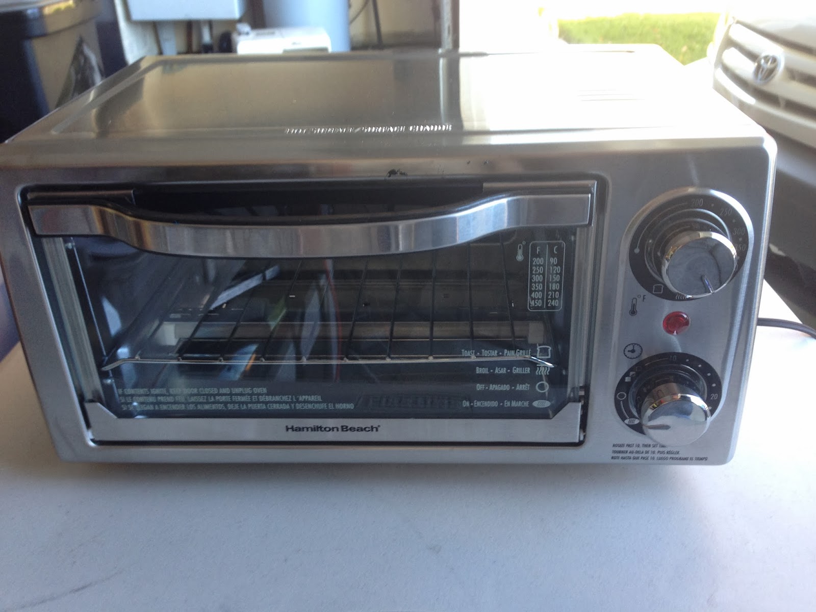
While I was ordering the parts, I bought a thermocouple probe and amplifier chip. I then went to Fry's and bought a Hamilton Beach model 31138. From examining it on the shelf, it looks like it's going to be reasonably easy to disassemble and modify. But before I make it impossible to return, I wanted to test it. I put the thermocouple in the oven and set it to 450 and turned it on.
It took 90 seconds to get to 50 degrees (all measurements are in Celsius. I'm going to stop saying that now), a further 67 seconds to get to 100, 78 more seconds to get to 150, 96 more seconds to get to 200 and then 63 seconds to get to 225. I turned off the heat at that point and the oven took 4:50 to fall down to 150 degrees.
At first glance, that doesn't look like very good performance, but the slow cooling has made me think that the problem is that the thermocouple is not agile enough. So I'm going to get a different one (this time not embedded in a big metal probe) and try again.
Meanwhile, I decided to go for broke. The oven is very easy to disassemble with just a philips screwdriver.


The left inside - the front is to the right.

The right inside, where the controls are.

Here are the wires of interest: red is hot, white is top element, blue is bottom. The rest don't matter.

Check the wiring... The hot line goes directly to the red QD on the table. The neutral line goes to the indicator light on the front panel and to the two elements on the far side of the oven. We won't bother hooking the hot side of the light to anything, so those two QDs will be wrapped in tape to keep them out of mischief.
There is a single piece of sheet stainless steel wrapped around the sides and top of the oven. You need to pull all of the screws on the back that hold this piece in place. There's one screw near the left (viewed from the front) rear bottom that also must be removed. Next, pop out the rubber inserts in each of the plastic feet and unscrew and remove the screws inside as well as the two larger philips screws between the feet. That done, the top/side sheet should pop right off.
Once that's done, cut and remove the two "rat belts" bundling the wires near the AC plug and near the top. Use a flat screwdriver and pop the QD connectors (each is inside a redish-brown rubber heat shield) attaching all of the wires to the controls. You'll wind up with one coming from the top element, one coming from the bottom element, and one coming from the hot line of the AC plug. There are some other QDs, but they won't be used.
1 comment:
Great project Nick, but if you want a far less expensive and better quality stencil you should check out OSH Stencils www.oshstencils.com we switched to them a while ago and have been very happy.
Post a Comment